Peripheral Parallel Interface for Parallel Port
- Introduction
- I've built this interface to have a simple way to interface a personnal computer with various home made devices. This circuit has been designed to be connected to the PC parallel port and provides 24 I/O lines. It uses a 8255 (originally manufactured by Intel). As we will see later, the circuit is very simple and does not require special components. I also provide code (written in C) to give you the ability to use this interface in your applications under Linux, DOS and Windows. The only restriction, for the moment, is that you need an IBM compatible computer to use it : the hardware has to be accessed at the I/O port level and I don't have the (parallel port) documentation for other platforms.
- Hardware
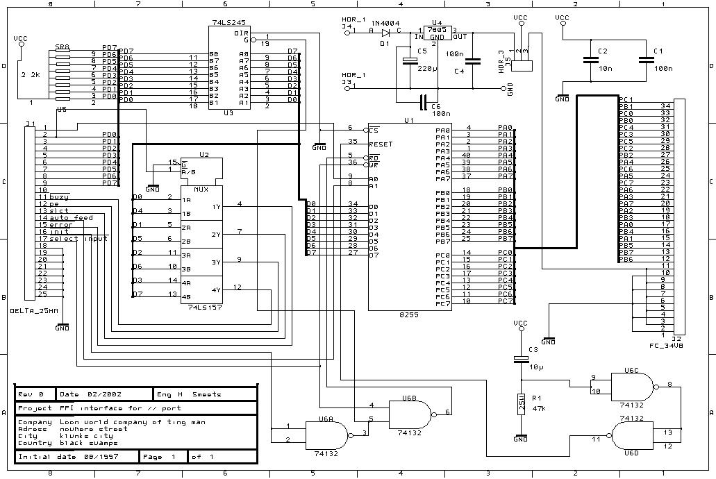
- The hardware is very simple, see the schematic below. U3 is a buffer for the D0..7 signals from the parallel port. SR8 is a 2.2K resistors network ; it defines the states of the D0..D7 lines when the device is not connected to a parallel port (or if the D0..D7 outputs on the PC side are open drain outputs). U2 is used to multiplex the data lines when the PC needs to read these lines (read operation on the 8255). The nibble to be read is selected by the PD0 line (comming from the parallel port). Various lines, originally intended to command a line printer, are used to perform an operation (read or write) on the 8255. As you can see, we have to drive these lines in an odd way and this requires to access the port registers directly (instead of using OS provided services). U6a and U6b are used to avoid any bus conflict (ie, U3 can not be enabled if a read operation takes place on the 8255). C3 and R1 place the 8255 in a known state after power-up. U6 has Schmidt trigger inputs so when C3 is being charged, the output of U6c will not oscillate. C1 and C2 are used for decoupling the power line. U4 provides the board with regulated 5 Volts. D1 protects the circuit from a polarity error while connecting an external power supply module (unregulated 8 to 30 Volts). HDR_1 (j4) should be connected to the (+) connection of a 220V->12V adaptor and HDR_1 (j3) to the its (-) connexion.
You can select the power supply source with the help of J5 wich in the 1-2 position, selects U4 and in the 2-3 position, selects a 5 Volts source comming from the application board (connected to J2). So the 8255 gives 3 I/O ports whom you can choose the direction by writing the right control word into the 8255. The datasheet of this chip can be found easily on the WEB (in google, type "8255 datasheet").
- Software
-
Here you can download an archive with the ppi software and more... but I don't support it for now, so you will be on your own.
- Links
-
Last modification : 05-16-2002
Hugues Smeets